![]()
Analysis of signal processing techniques commonly used for broken bars detection on induction motors
An�lisis de las T�cnicas de Procesamiento de Se�al com�nmente utilizadas para la Detecci�n de Barras Rotas en Motores de Inducci�n.
![]()
Danilo Granda1, Diego Arcos-Aviles2 & Danny Sotomayor2
1
Carrera de Ingenier�a
en Electr�nica, Automatizaci�n y Control, Departamento de El�ctrica y
Electr�nica, Universidad de las Fuerzas Armadas ESPE, 1715 231B, Sangolqu�,
Ecuador. Correo: [email protected]
2 Departamento de El�ctrica y Electr�nica, Universidad de las
Fuerzas Armadas ESPE, 1715-231B, Sangolqu�, Ecuador. Correo: [email protected]; [email protected]
Fecha de recepci�n: 30 de enero de 2018
Fecha de aceptaci�n: 19 de marzo de 2018
ABSTRACT
The fault detection of electric motors has been widely studied due to the importance of these devices at industrial level. This work presents the analysis of different signal processing techniques commonly used for broken bar detection of three-phase induction motors. Fast Fourier Transform (FFT), Hilbert Transform (HT), and Wavelet Transform (WT) are analyzed to obtain the motor current signal characteristics of healthy and faulty motors. The main advantages and drawbacks of each processing technique applied for broken bar detection of induction motors are presented in this study. The performance evaluation of each technique is carried out in the three-phase induction motor test bench at Universidad de las Fuerzas Armadas ESPE, Sangolqu�-Ecuador.
Keywords: Fault diagnosis, Induction motors, Signal processing, Fourier transform, Hilbert transform, Wavelet transform.
RESUMEN
La detecci�n de fallas de motores el�ctricos ha sido ampliamente estudiada debido a la importancia que presentan estos dispositivos a nivel industrial. Este trabajo presenta el an�lisis de diferentes t�cnicas de procesamiento de se�ales que son com�nmente utilizadas para la detecci�n de barras rotas de motores de inducci�n trif�sicos. Se analizan la Transformada r�pida de Fourier (FFT), la Transformada de Hilbert (HT) y la Transformada Wavelet (WT) para obtener las caracter�sticas de la se�al de corriente de motores sanos y defectuosos. En este estudio se presentan las principales ventajas y desventajas de cada t�cnica de procesamiento de se�al cuando es aplicada para la detecci�n de barras rotas en motores de inducci�n. La evaluaci�n del desempe�o de cada t�cnica se lleva a cabo de manera experimental a trav�s de un banco de pruebas desarrollado por la Universidad de las Fuerzas Armadas ESPE, Sangolqu�-Ecuador.
Palabras claves: Detecci�n de fallas, motores de inducci�n, procesamiento de se�ales, transformada de Fourier, transformada de Hilbert, transformada Wavelet.
INTRODUCCI�N
Induction motors have wide ranges of power, robustness, and reliability, so that, they are used in a variety of industrial processes [1], [2]. Induction motors commonly work in industrial environments and are exposed to severe operating conditions, such as, thermal stress, electromagnetic forces, electromagnetic noise, vibrations, centrifugal forces, and environmental stress, which cause the fatigue of motor internal parts [3] and increase the power consumption and the risk of motor failure. Therefore, early fault detection is required to concurrently minimize the load consumption and prevent stops of industrial production processes where induction motors are involved. In this regard, different processing techniques as well as several types of signal analysis (e.g., frequency domain analysis, instantaneous frequency, frequency-time analysis, multiresolution analysis) have been studied to perform an early fault detection of induction machines (e.g., stator winding faults, rotor broken bar, bearings damage) [2]�[8].
Motor Current Signal Analysis (MCSA) has been widely used, as a common data acquisition method, to implement several diagnosis techniques, since the current signal is acquired by a non‑invasive method simplifying its implementation in industrial environments [9]. In this context, Fast Fourier Transform (FFT), Hilbert Transform (HT), and Wavelet Transform (WT) are commonly used for fault diagnosis of induction machines [10]�[12].
In this regard, this work presents the analysis of different signal processing techniques used for broken fault detection of induction motors. The stator current signals are analyzed by means of FFT, HT, and WT highlighting advantages and disadvantages of each processing technique. The experimental analysis is performed in the induction motor test bench at Universidad de las Fuerzas Armadas ESPE, Sangolqu�‑Ecuador.
The rest of the paper is organized as follows. Section Methods describes the signal processing techniques used for broken bar detection and presents the experiment configuration setup. Next section presents the experimental results and the comparison of the analyzed techniques. Finally, the last section presents the main conclusion of this work.
���
METHODS
Spectral analysis �
����������� The signal spectral analysis is accomplished through the FFT [8], which transforms a signal from time domain to frequency domain. Since the FFT is easy to implement in Digital Signal Processing (DSP) systems [13], the FFT signal analysis is widely used in science, engineering, communication, metallurgy, applied mechanics, biomedical, and radar engineering. In fault diagnosis of induction machines, the FFT has been applied to analyze features of stator currents of healthy and faulty motors as in [4], [8].
Frequency-time analysis
����������� The Short-time Fourier Transform (STFT) is a particular application of FFT and it is used to analyze the signals in frequency-time domain. This transformation is applied to the analyzed signal to determine its fundamental frequency and harmonic components. The STFT allows analyzing the transient regime of induction motors [13] since it uses a fixed window for the signal analysis.
Instantaneous frequency analysis
����������� Since HT has the property of eliminating the negative frequencies of a signal while keeping the positive ones, the HT has been used as a filter in signal analysis applications. HT allows working in a low-frequency spectral region [5], leading a better frequency detection regarding the FFT analysis [13]. Concerning the motor fault diagnosis, the HT is used in [5] to perform the current analysis in transient and steady‑state regime for detecting faults in low slip motor.
Wavelet analysis
����������� The WT overcomes the STFT fixed window problems, since it uses scaled and dilated versions of the mother wavelet to obtain the transform. Researchers have been applied WT, both in discrete and continuous form, for fault detection on electric machines through the analysis of the motor starting current, and motor current during load changing [13]. Moreover, due to the advantage of multi-resolution analysis, WT has already shown its vast usefulness in fault diagnosis of rotating machinery [7].
Experimental setup
����������� The experimental analysis is accomplished in the three‑phase induction motor test bench installed at Universidad de las Fuerzas Armadas ESPE, Sangolqu�‑Ecuador. A complete description of motor test bench is presented in [14], [15]. However, the motor test bench description is presented and recalled next for the shake of paper completeness.
The block diagram of the induction motor test bench is shown in figure 1 and includes the following elements: a 1Hp three-phase ABB induction motor, a controllable load, three current sensors used to acquire the stator current signals, a tachometer used to measure the operating motor speed, a National Instruments (NI) NI cDAQ‑9184 data acquisition board, and a general-purpose PC used as a user interface and to perform the analysis of acquired signals. As mentioned in [15], the damage in each bar was produced by drilling 15 mm deep and 6 mm in diameter to ensure complete bar breaking [16]. For instance, figure 2 shows the damage generated in the rotor of an induction motors with three broken bars
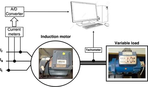
Figure 1. Induction motor test bench block diagram

Figure 2. Broken bar damage induced to the motor
The procedure used to analyze the different processing techniques applied for fault detection of induction motors is shown in figure 3. The procedure comprises four steps detailed as follows:
Step 1: To acquire the stator current signals Ir, Is, and It;
Step 2: To accomplish the pre-processing of acquired stator current signals (e.g., filtering, transient and steady-state extraction);
Step 3: To analyze the stator current signals (e.g., spectral analysis, frequency time, instantaneous frequency�) of healthy and faulty motor using different signal processing techniques (i.e., FFT, HT, and WT); and,
Step 4: To identify the induction motors fault by means of analyzing the harmonic components, energy variations, and spectral graphs of stator current signals.
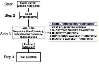
Figure 3. Induction motor broken bars detection process
EXPERIMENTAL RESULTS
The experimental results are obtained for a healthy motor and faulty motor with one, two, and three broken bars. Despite the next processing techniques can be used to detect any number of broken bars, only the comparison between a healthy and faulty motor with tree broken bars is presented below.
Fast Fourier transform
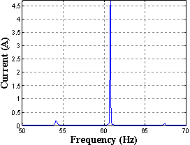
The spectrum analysis of motor current signals by means of FFT technique is accomplished when the motor is operating at steady-state, since the oscillations and instantaneous frequency changes produced by the motor drivers at its starting causes the overlapping of the harmonic components induced by the fault with the harmonic component of the utility grid [4], [8], which difficult the fault detection task. To avoid this overlapping, the machine should work with a minimum load level (e.g., motor operating at 35% of the nominal value) [5], [6].
Figure 4(a) and figure 4(b) show the current signal spectrum of a healthy and faulty motor, respectively, operating at full-load. The absence of harmonics components close to the motor operating frequency can be appreciated in figure 4(a). Conversely, two harmonic components can be seen when a faulty motor with three broken bars is analyzed, as shown in figure 4(b). Note that the grid power quality (i.e., grid frequency between 55 - 65Hz at the laboratory) leads to the motor operating frequency shifting.
 ��
�� 
����������������������������������� �(a)���������������������������������������������������������������� (b)
Figure 4. FFT spectrum of motor current signal operating at full load (a) healthy motor and (b) faulty motor with three broken bars
Short-time Fourier transform
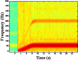
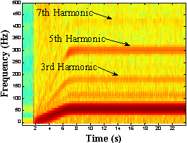
The frequency-time analysis is performed by the STFT using a Hamming, Bartlett, Blackman, or Chebyshev window of 256 samples. Due to the window response in the frequency domain, the window of Chebyshev presents better resolution regarding other windows. However, due to the use of a fixed window to perform the analysis, a resolution increase in frequency domain implies a resolution decrease in time domain [8]. Figure 5(a) and figure 5(b) show the analysis performed through the STFT in a healthy and a faulty motor, respectively. As it can be appreciated in figure 5(b), an increase in the magnitude of the current flowing through the bars that have not been affected (i.e., faulty motor) causes an increase in the magnitude of odd order harmonic components (i.e., third 180Hz, fifthly 300Hz, and seventhly 420Hz) with respect to figure 5(a).
 ��
�� 
����������������������������������� �(a)���������������������������������������������������������������� (b)
Figure 5. STFT of motor current signal operating at full-load (a) healthy motor and (b) faulty motor with three broken bars
Hilbert transform
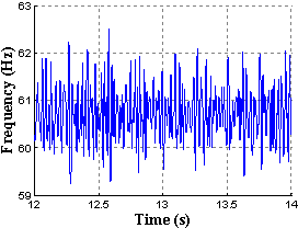
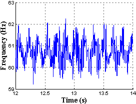
With respect to the FFT and STFT, Hilbert transform has mathematical properties which allow it to perform the analysis of instantaneous frequency and phase [5]. One of the drawbacks of this technique lies in the necessity of filtering the current signal to examine the frequency band and locate most of harmonic components of induction motor current signal. In this regard, the fault detection depends on the harmonic components variation of current signal. As it can be seen in figure 6, the harmonic components variation between a healthy motor, figure 6(a), and a faulty motor, figure 6(b), is small. Comparing with the FFT technique, the Hilbert transform presents a decrease in the amplitude of the harmonic components representing the fault.
 ��
�� 
����������������������������������� �(a)���������������������������������������������������������������� (b)
Figure 6. Instantaneous frequency of motor current signal operating at full load (a) healthy motor and (b) faulty motor with three broken bars
Continuous Wavelet transform
The Continuous Wavelet (CWT) overcomes the frequency‑time resolution disadvantages of STFT, since the analysis is performed with variable windows using the mother wavelet properties [7], [14]. For instance, the CWT with complex Morlet function performs an orthogonal analysis, using scales in powers of two (i.e., power of 2n). Thus, the time-frequency spectrum shows harmonic components according to the scale used in the analysis, which makes difficult the study of signals in motors with speed variations, as shown in figure 7.
 ��
�� 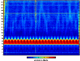
����������������������������������� �(a)���������������������������������������������������������������� (b)
Figure 7. CWT with complex Morlet function of motor current signal operating at full‑load (a) healthy motor and (b) faulty motor with three broken bars
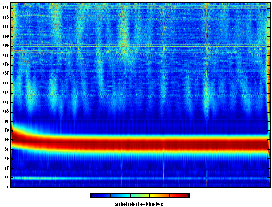
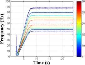
Conversely, Morlet-CWT is used for orthogonal and non‑orthogonal analysis of motor current signals. Consequently, different scales can be utilized according to study frequency [14]. In addition, this analysis allows observing frequency-time spectrum of larger extension in terms of signal acquisition intervals, since less computational resources are required by the Morlet-CWT algorithm. Figure 8(a) and figure 8(b) show the frequency-time spectrum of healthy and faulty motor, respectively, operating at full load [14]. As it can be seen, the presence of broken bars is observed as oscillations in the current signal spectrum shown in figure 8(b).
 ��
�� 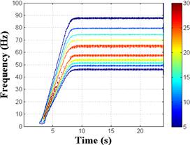
����������������������������������� �(a)���������������������������������������������������������������� (b)
Figure 8. Morlet-CWT of motor current signal operating at full load (a) healthy motor and (b) faulty motor with three broken bars
Discrete Wavelet transform
The analysis of current signals through WT can be accomplished using different kinds of mother wavelet (e.g., Daubechies, Coiflet, Symlet, Dmeyer), which decomposes the current signal at different levels known as approximation and detail coefficients [17]. As shown in figure 9, Daubechies44 mother wavelet of nine decomposition levels is used to analyze the current signal of a faulty motor.
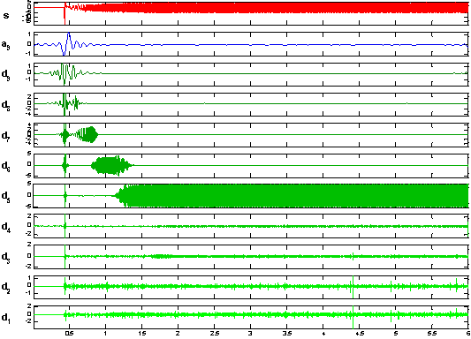
Figure 9. Multiresolution wavelet decomposition of the current signal of a faulty motor
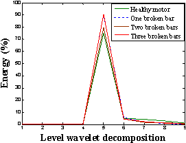
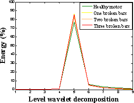
Moreover, Daubechies44 and Symlet20 mother wavelet has similar characteristics when decomposition levels are analyzed, as shown in figure 10 [healthy motor figure 10(a) and faulty motor Fig. 10(b)]. However, the suitable selection of mother wavelet leads to efficient results [14].
 ��
�� 
����������������������������������� �(a)���������������������������������������������������������������� (b)
Figure 10. Energy coefficients wavelet decomposition of current signal for a healthy and faulty motor a) Daubechies44 and b) Symlet20
Finally, table 1 summarizes the signal processing techniques capabilities, achieved from experimental results, for broken bar detection in induction machines. As it can be seen, the WT is a powerful technique which can be used in transients and steady-state conditions.
Table 1. Summary of signal processing techniques commonly used for broken bar detection of induction machines
|
Signal Processing Techniques |
Analysis conditions |
||||
|
No-load operation |
Full-load operation |
Transient signals |
Steady-state |
Torque oscillations |
|
|
FFT |
|
X |
|
X |
|
|
SFFT |
|
X |
X |
X |
|
|
HT |
|
X |
X |
X |
X |
|
WT |
X |
X |
X |
X |
X |
DISCUSSION AND CONCLUSION
����������� This paper has presented a short analysis of signal processing techniques used for broken bars detection of induction motors.� Advantages and drawbacks of each technique have been presented in order to identify their potentialities. STFT, CWT, and DWT are used to identify failures at motor starting, since they use a time-sliding window to examine the motor current signals. In addition, Hilbert transform performs instantaneous frequency analysis. The experimental results allow concluding that the fault quantification is not determined when Hilbert transform or Complex-WT is used in fault detection process. Therefore, these techniques could be used to alert the system about the existence of a fault. Conversely, FFT, Morlet-CWT, and DWT allow quantifying the number of broken bars, so that, they have greater application at industrial level.
FUENTES DE FINANCIAMIENTO
����������� This work is part of the project No. 2013-PIC-019 from Universidad de las Fuerzas Armadas ESPE, and has been developed by the Propagation, Electronic Control and Networking - PROCONET and Wireless Networks - WICOM Energy Research Groups.
DECLARACI�N DE CONFLICTO DE INTER�S
����������� The authors declare no conflict of interest.
APORTE DEL ART�CULO EN LA L�NEA DE INVESTIGACI�N
����������� This article presents a summary of the main signal processing techniques that are commonly used for broken bars detection in three-phase induction motors. It presents the experimental results of each processing technique, with which the reader can determine the advantages and disadvantages of each of them.
DECLARACI�N DE CONTRIBUCI�N DE CADA AUTOR
����������� The authors conceived and designed the experiments. D.S. built the motor test bench. D.G. performed de experiments. D.G., D.A.A. and D.S. performed the analysis of experimental results and wrote the paper.
REFERENCIAS
[1] O. Ondel, E. Boutleux, and G. Clerc, �A method to detect broken bars in induction machine using pattern recognition techniques,� IEEE Trans. Ind. Appl., vol. 42, no. 4, pp. 916�923, Jul. 2006.
[2] P. Karvelis, G. Georgoulas, I. P. Tsoumas, J. A. Antonino-Daviu, V. Climente-Alarcon, and C. D. Stylios, �A Symbolic Representation Approach for the Diagnosis of Broken Rotor Bars in Induction Motors,� IEEE Trans. Ind. Informatics, vol. 11, no. 5, pp. 1028�1037, Oct. 2015.
[3] A. Bellini, F. Filippetti, C. Tassoni, and G.-A. Capolino, �Advances in Diagnostic Techniques for Induction Machines,� IEEE Trans. Ind. Electron., vol. 55, no. 12, pp. 4109�4126, Dec. 2008.
[4] T. Yang, H. Pen, Z. Wang, and C. S. Chang, �Feature Knowledge Based Fault Detection of Induction Motors Through the Analysis of Stator Current Data,� IEEE Trans. Instrum. Meas., vol. 65, no. 3, pp. 549�558, Mar. 2016.
[5] R. Puche-Panadero, M. Pineda-Sanchez, M. Riera-Guasp, J. Roger-Folch, E. Hurtado-Perez, and J. Perez-Cruz, �Improved Resolution of the MCSA Method Via Hilbert Transform, Enabling the Diagnosis of Rotor Asymmetries at Very Low Slip,� IEEE Trans. Energy Convers., vol. 24, no. 1, pp. 52�59, Mar. 2009.
[6] J. Cusid�, L. Romeral, J. A. Ortega, A. Garcia, and J. Riba, �Signal injection as a fault detection technique,� Sensors, vol. 11, no. 12, pp. 3356�3380, Mar. 2011.
[7] J. Chen, Z. Li, J. Pan, G. Chen, Y. Zi, J. Yuan, B. Chen, and Z. He, �Wavelet transform based on inner product in fault diagnosis of rotating machinery: A review,� Mech. Syst. Signal Process., vol. 70�71, pp. 1�35, Mar. 2016.
[8] A. Sapena-Bano, M. Pineda-Sanchez, R. Puche-Panadero, J. Martinez-Roman, and D. Matic, �Fault Diagnosis of Rotating Electrical Machines in Transient Regime Using a Single Stator Current�s FFT,� IEEE Trans. Instrum. Meas., vol. 64, no. 11, pp. 3137�3146, Nov. 2015.
[9] M. J. Picazo-Rodenas, J. Antonino-Daviu, V. Climente-Alarcon, R. Royo-Pastor, and A. Mota-Villar, �Combination of Noninvasive Approaches for General Assessment of Induction Motors,� IEEE Trans. Ind. Appl., vol. 51, no. 3, pp. 2172�2180, May 2015.
[10] W. T. Thomson and M. Fenger, �Current signature analysis to detect induction motor faults,� IEEE Ind. Appl. Mag., vol. 7, no. 4, pp. 26�34, Aug. 2001.
[11] J. Rangel-Magdaleno, J. Ramirez-Cortes, and H. Peregrina-Barreto, �Broken bars detection on induction motor using MCSA and mathematical morphology: An experimental study,� in IEEE International Instrumentation and Measurement Technology Conference (I2MTC), Minneapolis, MN, EEUU, May 2013, pp. 825�829.
[12] S. H. Kia, H. Henao, and G.-A. Capolino, �Diagnosis of broken-bar fault in induction machines using discrete wavelet transform without slip estimation,� IEEE Trans. Ind. Appl., vol. 45, no. 4, pp. 1395�1404, Jul. 2009.
[13] S. Karmakar, S. Chattopadhyay, M. Mitra, and S. Sengupta, Induction Motor Fault Diagnosis. Singapore: Springer Singapore, 2016.
[14] D. Granda, W. G. Aguilar, D. Arcos-Aviles, and D. Sotomayor, �Broken Bar Diagnosis for Squirrel Cage Induction Motors Using Frequency Analysis Based on MCSA and Continuous Wavelet Transform,� Math. Comput. Appl., vol. 22, no. 2, p. 30, Apr. 2017.
[15] D. Sotomayor, S. Castellanos, D. Arcos-Aviles, and D. Benitez, �A computer-aided test bench system for teaching and research on fault detection in three-phase induction motors,� in IEEE 37th Central American and Panama Convention (CONCAPAN XXXVII), Managua, Nicaragua, Nov. 2017, pp. 1-6
[16] C. E. Talbot, P. N. Saavedra, and M. A. Valenzuela, �Diagn�stico de la Condici�n de las Barras de Motores de Inducci�n,� Inf. tecnol�gica, vol. 24, no. 4, pp. 19�20, Jul. 2013.
[17] M. R. Mehrjou, N. Mariun, M. Karami, S. B. M. Noor, S. Zolfaghari, N. Misron, M. Z. A. A. Kadir, M. A. M. Radzi, and M. H. Marhaban, �Wavelet-Based Analysis of MCSA for Fault Detection in Electrical Machine,� in Wavelet Transform and Some of Its Real-World Applications, InTech, Dec. 2015.
BIOGRAPHY

He received B.S degree in Electronics, Automation and Control Engineering from Universidad de las Fuerzas Armadas ESPE, Sangolqu�, Ecuador, in 2017. His research interests are electronics engineering, electrical engineering, induction motors and control systems engineering.

He received the B.Sc. degree in Electronics, Automation and Control Engineering from Universidad de las Fuerzas Armadas ESPE, Sangolqu�, Ecuador, in 2002, the M.Sc. and PhD. degrees in Electronics Engineering from Universitat Polit�cnica de Catalunya, Barcelona, Spain, in 2012 and 2016, respectively. His research interests include microgrid energy management, power electronics, microgrids, and renewable power generation.

He received the B.Sc. degree in Electronics, Automation and Control Engineering from Universidad de las Fuerzas Armadas ESPE, Sangolqu�, Ecuador, in 2001 and the M.Sc. degree in Design, Production and Industrial Automation from Escuela Polit�cnica Nacional, Quito, Ecuador, in 2016. He is currently pursuing the Ph.D. degree in Signal Processing at Universidad Rey Juan Carlos, Madrid, Espa�a. His research interests include signal processing, detection and classification algorithms, support vector machine and machine learning.
![]()
Esta obra est� sujeta a la Licencia Reconocimiento-SinObraDerivada 4.0 Internacional de Creative Commons. Para ver una copia de esta licencia, visite http://creativecommons.org/licenses/by-nd/4.0/ o env�e una carta Creative Commons, PO Box 1866, Mountain View, CA 94042, USA.